Check Inventory & Get a Quote
| Product | Description | Part Number | Resin | Color | Length | Location | Pieces |
|---|
|
Span (inches) |
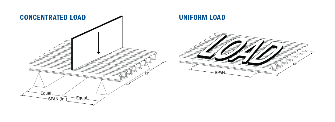
CONCENTRATED LOAD in lb/ft of width |
Max |
Apparent |
|||||||
|
50 |
100 |
150 |
200 |
250 |
500 |
1000 |
2000 |
|||
|
12 |
0.002 |
0.003 |
0.005 |
0.007 |
0.008 |
0.016 |
0.033 |
0.065 |
5755 |
1.10 |
|
18 |
0.004 |
0.009 |
0.013 |
0.018 |
0.022 |
0.044 |
0.088 |
0.176 |
3850 |
1.38 |
|
24 |
0.009 |
0.019 |
0.028 |
0.037 |
0.047 |
0.094 |
0.187 |
0.374 |
2888 |
1.54 |
|
30 |
0.017 |
0.035 |
0.052 |
0.069 |
0.086 |
0.173 |
0.345 |
0.690 |
2310 |
1.63 |
|
36 |
0.029 |
0.059 |
0.088 |
0.117 |
0.146 |
0.293 |
0.586 |
1925 |
1.66 |
|
|
42 |
0.046 |
0.092 |
0.138 |
0.184 |
0.230 |
0.459 |
1650 |
1.68 |
||
|
48 |
0.068 |
0.136 |
0.203 |
0.271 |
0.339 |
0.678 |
1444 |
1.70 |
||
|
54 |
0.095 |
0.191 |
0.286 |
0.381 |
0.477 |
1283 |
1.72 |
|||
|
60 |
0.129 |
0.259 |
0.388 |
0.517 |
0.647 |
1155 |
1.74 |
|||
|
66 |
0.171 |
0.342 |
0.513 |
0.685 |
1050 |
1.75 |
||||
|
72 |
0.221 |
0.442 |
0.663 |
962 |
1.76 |
|||||
|
Span (inches) |
UNIFORM LOAD in lb/ft2 |
Max |
Apparent |
|||||||
|
50 |
100 |
150 |
200 |
250 |
500 |
1000 |
2000 |
|||
|
12 |
0.001 |
0.002 |
0.003 |
0.004 |
0.005 |
0.010 |
0.020 |
0.041 |
7944 |
1.10 |
|
18 |
0.004 |
0.008 |
0.012 |
0.017 |
0.021 |
0.041 |
0.083 |
0.165 |
5296 |
1.38 |
|
24 |
0.012 |
0.023 |
0.035 |
0.047 |
0.058 |
0.117 |
0.234 |
0.468 |
2935 |
1.54 |
|
30 |
0.027 |
0.054 |
0.081 |
0.108 |
0.135 |
0.270 |
0.539 |
1845 |
1.63 |
|
|
36 |
0.055 |
0.110 |
0.165 |
0.220 |
0.274 |
0.549 |
1281 |
1.66 |
||
|
42 |
0.100 |
0.201 |
0.301 |
0.402 |
0.502 |
943 |
1.68 |
|||
|
48 |
0.169 |
0.339 |
0.508 |
0.678 |
721 |
1.70 |
||||
|
54 |
0.268 |
0.536 |
571 |
1.72 |
||||||
|
60 |
0.404 |
514 |
1.74 |
|||||||
|
Properties Per Foot of Width |
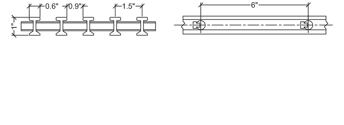
# of Bars |
Load Bar Depth |
Bar Centers |
Weight/sq ft |
|
A = 2.44 in2 I = 0.31 in4 S = 0.62 in3 |
8 |
1″ |
1.5″ |
2.47 |
1. Tables were developed in accordance with the test method developed by the Fiberglass Grating Manufacturers Council (FGMC) of the American Composites Manufacturers Association (ACMA) for the Fiberglass Grating Standard.
2. The designer should not exceed MAXIMUM RECOMMENDED load at any time. ULTIMATE CAPACITY represents MAX LOAD observed at initial fracture.
3. Walking loads for maintenance traffic are typically a live load of 50 PSF. Deflections for worker comfort are typically limited to 0.375″ (3⁄8″) or SPAN divided by 120 under full live load. For a firmer feel under full live load or a line load 250 lb/ft of width, limit deflections to 0.25″ (1/4″) or SPAN divided by 200.
4. The loads represented are for STATIC LOAD CONDITIONS at ambient temperature. Deflections for impact loads or dynamic loads will MULTIPLY the deflections shown by 2. Long term loads will result in added deflection due to creep in the material and will require higher factors of safety to ensure acceptable performance.
5. Deflections are limited to 0.5″ (1/2″) as recommended by the Fiberglass Grating Manufacturers Council of the American Composites Manufacturers Association.
Add to Cart: I 10-60 – I Bearing Bar